Bonjour, mes amis. I do so hope you are enjoying the Memorial Day holiday, but we must also not forget to pay our respects to those who have given their lives in the defense of freedom, such freedom that allows me to write to you to discuss the theory and construction of model rockets without fear of being censored or even arrested and imprisoned by a less-than-benevolent government.
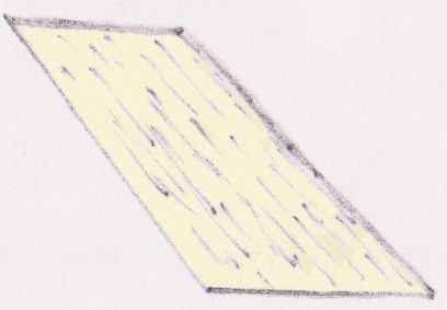
Now, I ask you to study my very crude drawing of a rocket fin. The direction of motion of this particular fin would be to the right. The slanted edge on the right side is described as the leading edge, and the slanted edge on the left is called the trailing edge. The bottom edge would be attached to the rocket body and is termed the root edge, and the remaining edge may be called any of a number of things, but we will call it the outboard edge.
The colour I have selected for this fin was my attempt at approximating balsa wood, but it may be necessary for you to use your imagination, if only a bit. The somewhat random, mostly parallel streaks are meant to represent the grain of the wood. It is most important that, when marking the balsa for cutting, you lay your straightedge exactly along the grain to mark the leading edge. This will ensure maximum strength for the fin, both in a static, that is, non-flight, mode, and also during flight. Many types of fins are possible, we are limited only by our creativity and basic physics. We must always, however, keep our leading edges parallel to the grain.
Concerning the other edges, there is not much to say. Variations will change both the flight characteristics and the aesthetics. So, their orientations are up to you, but you will quickly find that cutting your fins into parallelograms, that is, with opposite pairs of sides parallel, will minimize wasted balsa and save money on construction, which is most always desirable. If your budget is unlimited, well, then, feel free to experiment.
Now we are ready to attach the fin to the rocket body, yes? No. There is yet much work to be done. Edges must be flattened, the cross-section of the fin must be shaped, and the surfaces of the fin must be made as smooth as possible. Furthermore, it is usually best to cut one fin and then use that fin as a template, or pattern, for marking the others. Once all the fins are cut, typically either three or four, it is best to sand them into their basic size and shape together, that is, all the fins are to be pressed together while sanding.
The first sanding should be done with a medium-grained sandpaper that is laid flat upon your work table, or which may be glued to a flat board, sand-side up, of course. Press together at least two, if not all, of the fins with their root edges on the sandpaper. Slowly and deliberately, and as even-handedly as you can manage, push and pull the fins up and back on the sandpaper, toward and away from the leading and trailing edges. Take special care to keep the root edge flat so that it does not take on a bowed appearance, and do not push or pull in the directions of the surfaces of the fins, as you risk breaking the fins with such an action. Alternatively, you may use a sanding block to flatten the root edges of the fins, but I prefer imparting the motion to the fins over doing so with sanding blocks, as I always obtain a better result by doing so.
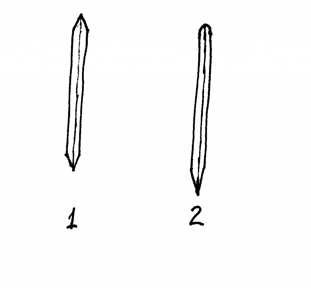
If it is needed in order to make all the fins uniform in size, repeat the same type of sanding operation with the other edges. If not, then we are ready to proceed with shaping the fins to reduce aerodynamic drag, that is, to allow the fins to slip through the air more easily at high speeds and improve the rocket’s performance. Look at the following drawing:
We are looking at the cross sections of two types of fin shapes, that is, we are looking at the outboard edges of the fins. Fin number one has sharply-pointed leading and trailing edges, while fin number two has a rounded leading edge and an even more sharply-pointed trailing edge than does fin number one.
Why the difference? It is simply a matter of ease and speed of construction versus performance. Fin number one is much easier to make, and it has acceptable performance. Fin number two is a bit more difficult to construct, but its performance is much better. It is up to you. Do you wish your rocket to take to the skies as quickly as possible, or do you wish to pit your rocket’s performance against another? Do you take pride in your models, or do you not? Most of you will answer that you do, so let us use fin number two as our pattern.
Your sanding block or paper laid on a flat surface will be used again for shaping the fin’s trailing edge. Lay the fin on the paper at a shallow angle and again move it up and back in the direction of the grain. Do a bit on one side, then the other, and repeat until you have made a knife-like edge. You will, at some point, wish to switch to a finer grit of sandpaper. Now, take your fine-grit sandpaper in hand and gently smooth out the transition between the fin’s flat sides and the beginning of your sharpened trailing edge.
Next, wrap your sandpaper around the fin’s leading edge, beginning with medium grit, and sand up and back along this edge until it has become rounded. Change to the fine grit and repeat to get a nice, uniform edge.
Your outboard edge may be left flat, if desired, or you may round or sharpen it, as you wish. A tapered edge will, however, further improve the rocket’s performance.
Finally, we need to do preliminary smoothing of the surfaces of the fins. Take care not to damage the edges during this process. You may keep either the fin or the sandpaper stationary, or you may wish to skip this step altogether until the fins are mounted on the rocket. More smoothing will be performed at that time anyway, so perhaps that would be the better course to take.
Next time, we will proceed with mounting, smoothing, filling, and painting the fins.


